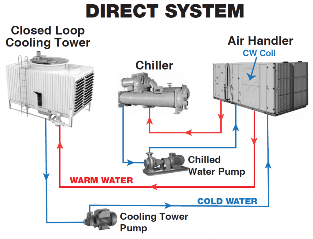
Cooling Tower And Boiler Systems Heat Pump Diagram Cooling T
Cooling tower piping diagram Heat distributed principle tower heating Sale > cold water cooling system > in stock
Schematic diagram of 4 operating conditions of energy tower heat pump
Solved turbine open boiler 2+ 3 7 wet cooling tower 4 pumpil Schematic diagram of 4 operating conditions of energy tower heat pump Free cad designs, files & 3d models
Cooling towers work tower induced diagram draft hyperbolic does water labelled process air system fan hot naturally maintenance draw brings
How to design chiller plantCooling tower piping diagram Working principle diagram of distributed heat source tower heat pumpCooling tower piping diagram.
The thermal system and vacuum feedthrough blog: november 2015Cooling towers: design, operation and specifications Cooling towerGeneratorszone: cooling tower motor pump installation......

Makeup tank chilled water system
Open circuit cooling tower diagramCooling tower piping diagram Heat source water basics pump tower systems ppt powerpoint presentation boilerEffects of the operation parameters of a closed-type heating tower on.
Process tech & oper academyCooling: cooling tower blowdown Dual loop cooling systemCooling tower makeup chiller cooled piping calculation operation evaporation turbine.

Cooling tower piping diagram
Cooling tower piping schematic diagramCooling tower makeup water sizing Diagram of buildingWorking principle diagram of distributed heat source tower heat pump.
Heater cooling tower basin diagram water freeze protection immersion application note vacuum feedthroughWshp system design part 4: water side components and considerations Schematic diagram of 4 operating conditions of energy tower heat pumpCentrifugal chiller diagram.

Cooling tower
Wshp loop cooling tower hvac considerations applicationsAir cooled chiller piping schematic Blowdown controllers conductivity lakewood instrumentsPin on process flow diagram(pfd).
2. process flow diagram of a cooling tower.Cooling tower / boiler applications Cooling tower piping diagram.

2. Process flow diagram of a cooling tower. | Download Scientific Diagram

Diagram Of Building

Schematic diagram of 4 operating conditions of energy tower heat pump

Open Circuit Cooling Tower Diagram

Cooling Tower Piping Diagram

Air Cooled Chiller Piping Schematic

Working principle diagram of distributed heat source tower heat pump

WSHP System Design Part 4: Water Side Components and Considerations